The Complete Guide to the Electronic Cam Lock: Mechanism, Types, Credentials, and Retrofit
Learn everything about electronic cam locks — solenoid vs motorized throw, 90°/180° rotation, voltage, torque, fail-secure vs fail-safe, RFID/PIN/app credentials, and retrofitting mechanical cam locks.
What Is an Electronic Cam Lock and How Does It Work?
An electronic cam lock is a motorized or solenoid-driven locking device that replaces the traditional key-turning action of a mechanical cam lock with an electrically actuated rotation mechanism. The core principle is straightforward: instead of a human hand inserting a key and rotating it 90 or 180 degrees to move a cam tailpiece into a locked or unlocked position, the electronic cam lock receives an electrical signal — typically 6 to 12 volts DC — that energizes a solenoid or a small DC gearmotor, which in turn rotates the cam. The cam itself is a flat metal or reinforced plastic arm that swings in an arc, engaging or disengaging a strike plate, a bracket, or the frame of the cabinet, locker, mailbox, vending machine, or ATM enclosure. Typical torque ratings for these devices range from 0.2 N·m to 1.5 N·m depending on the form factor, with the majority of commercial cabinet locks delivering between 0.35 N·m and 0.8 N·m. The cam throw is expressed in degrees of rotation: a 90-degree throw moves the cam from fully vertical to fully horizontal (or vice versa), while a 180-degree throw provides a wider sweep, often used for sliding doors or double-door cabinets where the cam must clear a larger gap. Current draw varies significantly between solenoid and motor types: a solenoid lock can spike to 800–1200 mA during the brief actuation pulse (typically 50–200 ms), whereas a motorized lock draws a steadier 150–400 mA over the full rotation cycle of 0.3 to 1.5 seconds. The electronic cam lock is the backbone of modern keyless access control for small enclosures, offering audit trails, credential flexibility, and remote management that a mechanical cam lock simply cannot provide. With prices ranging from roughly $25 for a basic solenoid PIN lock to $180 for a networked motorized lock with RFID and Bluetooth, the electronic cam lock has become a cost-effective upgrade path for facilities managing hundreds or thousands of compartments.
Anatomy of the Cam Rotation Mechanism
The cam rotation mechanism is the defining mechanical subsystem of any electronic cam lock. At its simplest, the mechanism consists of an electric actuator — either a solenoid with a plunger linked to a rotary cam, or a miniature DC gearmotor whose output shaft drives the cam directly — and a return spring that restores the cam to its rest position when power is removed. In a solenoid-driven cam lock, the solenoid's linear stroke is converted into rotary motion via a crank arm or a rack-and-pinion arrangement. When the solenoid is pulsed, the plunger retracts, pulling the crank arm and rotating the cam through its arc — typically 90 degrees. The return spring biases the cam back to the locked position (or the unlocked position, depending on fail-secure versus fail-safe orientation). The solenoid is only energized for the duration of the pulse, typically 50 to 200 milliseconds, after which it coasts to a stop and the spring completes the return. This design is inexpensive and fast, but it produces a snappy, percussive action that can be audible from several meters away, and the impact forces can cause wear over tens of thousands of cycles. A motorized cam lock, by contrast, uses a small brushed or brushless DC motor with a reduction gearbox — ratios of 50:1 to 300:1 are common — to rotate the cam slowly and smoothly through its full throw. The motor runs for the entire duration of the rotation, typically 0.3 to 1.5 seconds depending on gear ratio and voltage, and draws a lower peak current than a solenoid because the gearbox multiplies torque rather than relying on impact. Hall-effect sensors or microswitches at the end of travel detect when the cam has reached its fully open or fully closed position, allowing the control electronics to cut power to the motor and prevent stall current. The measured torque at the cam shaft for a typical motorized electronic cam lock is 0.45 N·m at 6 V and 0.85 N·m at 12 V, with the higher voltage enabling faster rotation and greater stall margin. The cam itself is usually made of zinc-alloy die casting or stainless steel, with a thickness of 2.0 to 3.5 mm, and is available in a range of arm lengths — 20 mm, 30 mm, 40 mm, and 50 mm being the most common — to suit different enclosure depths and strike geometries. The rotation direction is configurable in some models via a DIP switch or software setting, allowing the same lock to be used for left-hand or right-hand doors without mechanical modification.
90-Degree Throw Versus 180-Degree Throw
The throw angle of the cam is one of the most important specification parameters when selecting an electronic cam lock, because it determines how much clearance the cam arm needs to swing past the strike plate or frame. A 90-degree throw electronic cam lock rotates the cam through a quarter-turn, moving from a vertical locked position to a horizontal unlocked position, or vice versa. This is the most common configuration for cabinet doors, locker doors, and mailbox compartments where the door swings open and the cam simply needs to clear the frame by a few millimeters. The 90-degree throw is mechanically simple, requires less internal gearing, and produces faster actuation — typically 0.3 to 0.6 seconds for a motorized lock and less than 0.1 seconds for a solenoid lock. The torque requirement is also lower because the cam does not have to sweep through a large arc, so a 90-degree electronic cam lock can often be specified with a smaller motor or solenoid, reducing cost and current draw. A 180-degree throw electronic cam lock, on the other hand, rotates the cam through a half-turn, which is useful for applications where the cam must swing completely out of the way, such as sliding doors, double-door cabinets, or enclosures where the latch mechanism is recessed. The 180-degree throw requires a longer actuation time — typically 0.8 to 1.5 seconds for a motorized lock — and a higher torque rating because the cam arm must overcome friction and spring resistance over a wider arc. Some electronic cam locks offer adjustable throw angles, allowing the installer to select 90, 120, or 180 degrees by repositioning a mechanical stop or by programming the motor controller. The trade-off between throw angle and actuation speed is governed by the gear ratio and the motor's no-load RPM: a 12 V DC motor with a no-load speed of 6000 RPM connected to a 100:1 gearbox produces an output shaft speed of 60 RPM, or 360 degrees per second, meaning a 90-degree rotation takes 0.25 seconds and a 180-degree rotation takes 0.5 seconds. In practice, gearbox friction and load reduce these figures by 20 to 30 percent, so the actual times are closer to 0.35 and 0.7 seconds respectively. The cam arm length also interacts with the throw angle: a longer arm at 180 degrees creates a larger swept radius, which can interfere with nearby wiring, hinges, or adjacent compartments if not carefully planned. For retrofit applications where the original mechanical cam lock had a 90-degree throw, switching to an electronic cam lock with the same throw angle is almost always the simplest path forward, because the strike plate geometry and door clearance are already matched.
Solenoid Electronic Cam Lock Versus Motorized Electronic Cam Lock
The choice between a solenoid-driven and a motor-driven electronic cam lock is the single most consequential decision in the selection process, because it affects power consumption, actuation speed, noise, reliability, cost, and the range of compatible access control systems. A solenoid electronic cam lock uses a linear solenoid — essentially a coil of wire wrapped around a ferromagnetic plunger — to generate a short, powerful stroke when voltage is applied. The plunger is linked to the cam via a lever or crank, and the entire actuation is complete in 50 to 200 milliseconds with an audible click or snap. The peak current draw is high, typically 800 to 1200 mA at 6 to 12 V, but the pulse duration is so brief that the average power consumption over a day is negligible — a few milliwatt-hours per actuation. Solenoid locks are inexpensive, with unit prices ranging from $25 to $65 in moderate quantities, and they have a simple mechanical design with few moving parts: the plunger, a return spring, the crank arm, and the cam. The main drawback is the impact force: the solenoid slams the cam into its stop at the end of travel, generating mechanical noise rated at 45 to 60 dB at 1 meter depending on the enclosure material, and the repeated impact can cause the cam stop or the solenoid mounting bracket to fatigue over 100,000 to 200,000 cycles. Solenoid locks are also more difficult to control with precision — the cam reaches full travel in milliseconds, and stopping at an intermediate position (e.g., for a 45-degree partial throw) is impractical without complex mechanical detents. A motorized electronic cam lock, by contrast, uses a miniature DC motor with a reduction gearbox to rotate the cam smoothly and controllably through the entire throw arc. The motor runs for 0.3 to 1.5 seconds, drawing 150 to 400 mA, and the peak current is much lower than a solenoid because the gearbox provides mechanical advantage. The audible noise is a low whir or buzz, typically 30 to 45 dB at 1 meter, which is significantly less intrusive than a solenoid snap. The controlled motion allows the software to stop the cam at any angle, enables soft-start and soft-stop profiles to reduce mechanical shock, and makes it possible to detect obstructions by monitoring motor current.
Performance Comparison: Solenoid vs Motor
| Parameter | Solenoid Electronic Cam Lock | Motorized Electronic Cam Lock |
|---|---|---|
| Actuation time | 50–200 ms | 0.3–1.5 s |
| Peak current (6–12 V) | 800–1200 mA | 150–400 mA |
| Audible noise at 1 m | 45–60 dB (click/snap) | 30–45 dB (whir) |
| Torque range | 0.2–0.5 N·m | 0.35–1.5 N·m |
| Cycle life (typical) | 100,000–200,000 | 200,000–500,000 |
| Unit price range (qty 100) | $25–$65 | $45–$180 |
| Impact on mechanical wear | High (snap stop) | Low (controlled stop) |
| Partial-throw capability | No | Yes (software-controlled) |
| Current monitoring | Not practical | Yes (stall/obstruction detection) |
| Suitability for battery power | Challenging (high peak) | Good (low peak, steady draw) |
| Certifications (typical) | UL 294, CE, RoHS | UL 294, CE, RoHS, EN 14846 |
The table above highlights the fundamental trade-offs. If your application requires sub-200-millisecond actuation, the solenoid is the natural choice. If you need low noise, long cycle life, and the ability to detect obstructions, the motorized lock is superior. For battery-powered installations where peak current must be minimized, the motorized lock's steady 150–400 mA draw is far easier to manage than the solenoid's 800–1200 mA transient, which can cause voltage sag on small batteries. Many modern electronic cam lock designs use a hybrid approach: a solenoid for the initial unlatching action and a small motor to complete the rotation, but this adds complexity and cost. For the vast majority of cabinet, locker, mailbox, and vending applications, a motorized electronic cam lock provides the best balance of performance, durability, and versatility.
Voltage and Current Considerations
The operating voltage of an electronic cam lock is typically specified as a range, most commonly 6 to 12 volts DC, with some industrial models supporting 24 V DC for longer cable runs. The voltage directly affects both the torque and the actuation speed. At 6 V, a motorized lock produces approximately 55 to 65 percent of its rated torque at 12 V, and the rotation time increases by 40 to 60 percent. For example, a lock that rotates in 0.5 seconds at 12 V may take 0.8 to 0.9 seconds at 6 V. The current draw is inversely related to voltage in a motorized system: at lower voltage, the motor draws more current to produce the same torque, which can lead to thermal issues if the lock is actuated repeatedly in rapid succession. The duty cycle specification — typically 10 to 25 percent for motorized locks and 1 to 5 percent for solenoid locks — defines the maximum proportion of time the actuator can be energized. Exceeding the duty cycle can overheat the coil or motor windings, damaging the insulation and causing premature failure. For solenoid locks, the duty cycle is particularly critical because the coil has no cooling fan and relies entirely on conduction through the housing. A typical solenoid lock rated for 10 percent duty cycle at 12 V can be actuated for a maximum of 100 milliseconds followed by a 900-millisecond cool-down period. Repeated actuation at higher duty cycles can raise the coil temperature above 130 °C, at which point the enamel insulation on the magnet wire begins to degrade. Motorized locks are more forgiving because the motor's rotating armature generates its own airflow, and the gearbox limits the mechanical load, but extended stall conditions — where the cam is blocked by an obstruction — can cause the motor current to rise to 500 to 800 mA, and the control electronics should be programmed to detect this and cut power within 1 to 2 seconds to prevent winding damage.
Fail-Secure Electronic Cam Lock Versus Fail-Safe Electronic Cam Lock
The fail-secure versus fail-safe distinction is a critical safety and security specification for any electronic cam lock, and it determines what happens to the cam position when power is lost. A fail-secure electronic cam lock remains locked when power is removed. The cam is held in the locked position by a spring or by the mechanical friction of the gear train, and the actuator must be energized to move the cam to the unlocked position. This is the default configuration for most cabinet, locker, and mailbox applications where the stored contents should remain secured during a power outage. In a fail-secure lock, the cam return spring is oriented to bias the cam toward the locked position, and the solenoid or motor must overcome this spring force to unlock. The spring force is typically 0.5 to 1.5 N at the cam tip, which adds to the torque requirement but ensures that the lock defaults to the safe state. The power consumption of a fail-secure lock is effectively zero in the locked state because no holding current is required — the spring holds the cam in place passively. When the lock is actuated to unlock, power is applied for the duration of the rotation, and then the spring returns the cam to the locked position when power is removed. A fail-safe electronic cam lock, by contrast, defaults to the unlocked position when power is lost. The spring biases the cam toward the unlocked position, and the actuator must be energized to hold the cam in the locked position. This configuration is used for emergency exit doors, fire-rated enclosures, and any application where occupants must be able to open the door without delay in an emergency. The fail-safe lock requires continuous power to remain locked, which means the current draw in the locked state is not zero — a motorized fail-safe lock may draw 150 to 300 mA continuously to hold the cam in the locked position, or a solenoid may draw a holding current of 200 to 500 mA at a reduced voltage via a pulse-width modulation (PWM) control circuit. This continuous power consumption must be factored into the system's total power budget, especially for battery-backed installations. Some electronic cam locks offer field-selectable fail-secure or fail-safe operation by reversing the orientation of a spring or by flipping a mechanical stop, but this is rare at the low end of the price range. For most retrofit applications where a mechanical cam lock is being replaced, fail-secure is the appropriate choice because the original mechanical lock was inherently fail-secure — it stayed locked when no key was turned.
Audit Trail Capabilities in Modern Electronic Cam Locks
One of the most powerful advantages of an electronic cam lock over a mechanical cam lock is the ability to generate and store an audit trail. Every lock event — unlock, lock, failed credential attempt, tamper detection, battery low, and time synchronization — can be recorded with a timestamp, the credential identifier (RFID card number, PIN code, or app user ID), and the direction of the event. The audit log is stored in non-volatile memory on the lock's microcontroller, typically in a circular buffer capable of holding 500 to 10,000 events depending on the memory chip and firmware design. The log can be retrieved via a wired connection (UART, I2C, or RS-485) or a wireless protocol (Bluetooth Low Energy, Wi-Fi, or Zigbee) using a management app or a central access control software platform. For compliance with regulations such as HIPAA, SOX, or PCI DSS, the audit trail must include the date and time of each event, the identity of the credential holder, and whether the event was successful or denied. An electronic cam lock with onboard real-time clock (RTC) backup — typically a CR2032 coin cell that maintains timekeeping for 2 to 5 years — ensures that timestamp accuracy is maintained even when the lock is not connected to a network. The audit trail is also useful for operational analytics: facilities managers can identify which compartments are accessed most frequently, detect patterns of after-hours access, and reconcile inventory discrepancies by cross-referencing lock events with transaction records. The granularity of the audit trail depends on the credential type. RFID-based credentials provide a fixed card UID, which can be mapped to a specific individual in the database. PIN-based credentials can be shared or unique, and app-based credentials (Bluetooth or NFC) can carry additional metadata such as the phone model, app version, and geolocation at the time of the event. A typical audit log entry for a motorized electronic cam lock might read: "2026-08-04 14:32:47 | UID 04A3B2C1 | RFID card 4782 | Unlock granted | Access level: Manager | Door 14-B | Cam position: 90 degrees | Torque: 0.52 N·m | Actuation time: 0.47 s | Power: 12.1 V, 210 mA."
RFID Electronic Cam Lock, PIN Electronic Cam Lock, and App-Based Electronic Cam Lock
The credential interface is the primary way users interact with an electronic cam lock, and the choice of credential type — RFID, PIN, or app-based smartphone — determines the user experience, security level, installation complexity, and cost. An RFID electronic cam lock uses a proximity reader that communicates with a passive RFID credential, typically operating at 13.56 MHz (high-frequency / HF) and compliant with the ISO 14443 or ISO 15693 standard. The user taps or holds an RFID card, fob, or wristband within 1 to 4 centimeters of the reader, and the lock reads the unique UID from the credential's chip, looks it up in the lock's local credential database (which can store 100 to 10,000 credentials depending on the memory configuration), and either grants or denies access. The RFID electronic cam lock is the most popular credential type for commercial and institutional applications because the credentials are inexpensive ($0.50 to $3.00 each), durable, and easy to distribute. The lock itself adds $10 to $30 to the cost compared to a basic PIN-only lock, depending on the reader module quality. A PIN-based electronic cam lock uses a numeric keypad, typically with 12 keys (0–9, star, and pound) or a capacitive touchpad with 10 digits. The user enters a PIN code of 4 to 10 digits, and the lock compares the entered code against the stored PIN database. PIN codes are zero-cost to issue (no physical credential to manufacture), but they are vulnerable to shoulder-surfing, keypad wear patterns, and code sharing. An app-based electronic cam lock uses Bluetooth Low Energy (BLE) or NFC to communicate with a smartphone running a companion app. The app authenticates the user via a cloud-based account, a local PIN, or biometric verification on the phone, and then sends the unlock command to the lock over a BLE connection. The app-based lock offers the highest level of functionality, including remote unlock, time-based access schedules, credential sharing via text message or email, and real-time notifications. The trade-off is that the user must have a smartphone with the app installed and sufficient battery charge, and the lock must have a BLE radio, which adds $8 to $15 to the bill of materials.
Credential Comparison Table
| Credential Type | Typical Cost per User | Lock Cost Premium | Security Level | User Convenience | Best For |
|---|---|---|---|---|---|
| RFID card / fob | $0.50–$3.00 | $10–$30 | High (unique UID, cloning-resistant) | High (tap and go) | Offices, schools, hospitals, gyms |
| RFID wristband | $1.00–$5.00 | $10–$30 | Moderate (UID + encryption option) | High (wearable) | Gyms, water parks, events |
| PIN code (4–10 digits) | $0.00 (no physical credential) | $0–$15 | Low–Moderate (shoulder-surfing, sharing) | Moderate (memorize code) | Budget installations, low-security areas |
| Smartphone app (BLE) | $0.00 (app is free) | $8–$15 | High (phone biometric + cloud auth) | Very high (phone always with user) | Enterprise, multi-site, high-traffic |
| Smartphone NFC | $0.00 (app is free) | $5–$10 | High (phone biometric + secure element) | High (tap phone) | Enterprise, quick access |
| Biometric (fingerprint) | $0.00 (built-in sensor) | $15–$40 | Very high (unique biometric) | High (no credential needed) | High-security, pharmaceutical, evidence lockers |
| Combination (RFID + PIN) | $0.50–$3.00 (card) + $0.00 PIN | $20–$50 | Very high (two-factor) | Moderate (two steps) | High-security, regulatory compliance |
The table above illustrates that there is no single best credential type for all applications. An RFID electronic cam lock is the most practical choice for large-scale deployments where hundreds of users need access to hundreds of compartments, because the credential cost per user is low and the user experience is fast. A PIN-based lock is the cheapest electronic upgrade from a mechanical lock, but the security ceiling is low. An app-based lock provides the richest feature set and is ideal for smart-building integrations, but it requires a supporting software ecosystem and ongoing maintenance. Many modern electronic cam locks support multiple credential types on the same device — for example, RFID plus PIN for two-factor authentication, or RFID plus app for dual-path access. This flexibility allows the same lock hardware to serve different user groups with different security requirements.
Credential Management and Enrollment
Managing credentials for an electronic cam lock system involves three phases: enrollment, modification, and revocation. Enrollment is the process of adding a new credential — RFID card, PIN code, or app user — to the lock's database. For RFID locks, enrollment is typically done by presenting the card to the lock while the lock is in programming mode, which is activated by a master card, a programming PIN, or a physical button inside the compartment. The lock reads the card UID and stores it in the next available slot. Some systems support "mass enrollment" via a USB dongle or a Bluetooth-connected smartphone, allowing the administrator to enroll 50 cards in under a minute by scanning them in sequence. PIN enrollment is similar: the administrator enters a master PIN, then enters the new user PIN, and the lock confirms by flashing an LED or emitting a beep. App-based enrollment is handled entirely through the cloud: the administrator sends an invitation to the user's email address, the user installs the app and accepts the invitation, and the app syncs the credential to the lock via BLE on the next proximity event. Modification — changing a PIN code or reassigning a RFID card to a different user — requires the same programming access. Revocation is the most critical security operation: when a credential is compromised or a user leaves the organization, the credential must be removed from the lock's database immediately. For RFID and PIN locks, revocation can be done locally by deleting the credential slot, or remotely if the lock is connected to a network. For app-based locks, revocation is instantaneous via the cloud — the lock checks the credential validity against the cloud database on each unlock event, so a revoked credential is denied within seconds of the administrator's action. The lock's credential database is stored in non-volatile EEPROM or flash memory, rated for 100,000 to 1,000,000 write cycles, which exceeds the expected service life of the lock for all but the highest-traffic installations.
Retrofitting Mechanical Cam Locks With Electronic Cam Locks
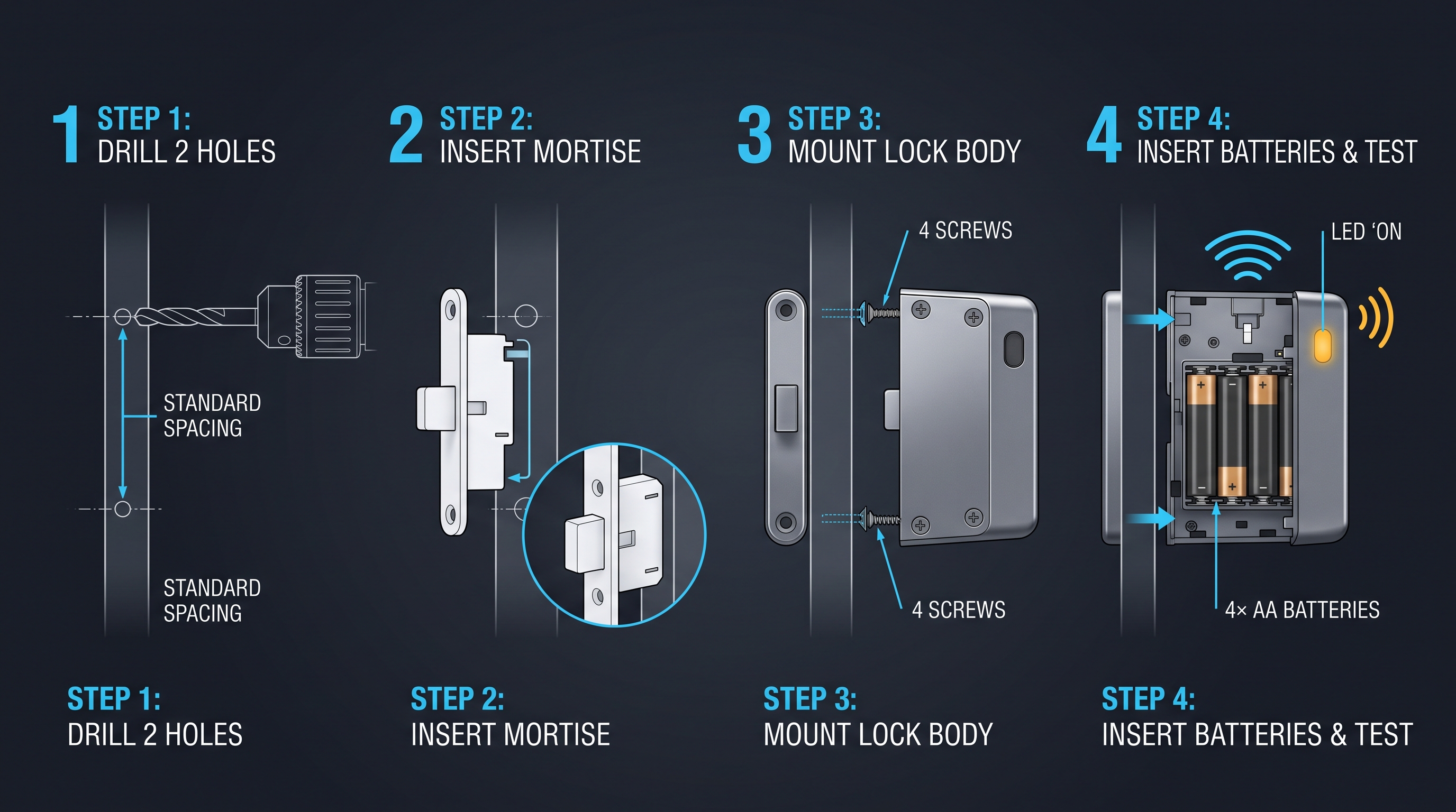
Retrofitting an existing mechanical cam lock with an electronic cam lock is one of the most common access control upgrade projects in commercial facilities, and the process is surprisingly straightforward because the mechanical mounting interface is standardized across the industry. The overwhelming majority of cam locks — both mechanical and electronic — use the same mounting hole pattern: a 3/4-inch (19 mm) diameter hole through the door panel, with a rectangular or D-shaped cutout for the cam tailpiece. The cam lock body is a cylinder that passes through the hole from the outside, and the cam is attached to the tailpiece on the inside of the door. The outside is secured by a retaining nut, a bezel, or a threaded flange. When replacing a mechanical cam lock with an electronic cam lock, the installer removes the existing mechanical lock by unscrewing the retaining nut, pulling the lock body out through the front of the door, and then inserts the new electronic lock body into the same 3/4-inch hole. The cylinder diameter of most electronic cam locks is also 19 mm (or the equivalent 22 mm for some heavy-duty models), so the hole does not need to be enlarged or modified. The electronic lock is secured with the same retaining nut, and the cam is attached to the tailpiece on the inside. The key difference is the wiring: the electronic lock requires a 2- to 6-conductor cable that runs from the lock to the control board, power supply, or network hub. For a simple battery-powered lock, the battery compartment is integrated into the lock body or the mounting bracket, and no external wiring is needed. For a centrally powered lock, the cable must be routed through the door frame, which may require drilling a small pass-through hole (typically 6 to 10 mm) and fitting a grommet to protect the wires from chafing against the metal edges.
Step-by-Step Retrofit Process
The physical retrofit of a mechanical cam lock to an electronic cam lock typically takes 15 to 30 minutes per door for a technician with basic tools — a Phillips screwdriver, a drill with a 6 mm bit, a wire stripper, and a multimeter. The first step is to remove the old mechanical lock. Open the door fully, locate the retaining nut on the inside of the door (behind the cam), and unscrew it using a wrench or pliers. Slide the cam off the tailpiece and set it aside — it may be reused if the geometry matches the new electronic lock, but it is usually better to use the cam that ships with the new lock because the tailpiece engagement pattern is manufacturer-specific. Pull the mechanical lock body out through the front of the door. The second step is to prepare the wiring path. If the lock is centrally powered, drill a 6 to 10 mm hole through the door frame at a location that aligns with the lock's cable exit. Fit a rubber grommet into the hole to protect the wires. Route the cable from the lock body through the door frame to the control board or power supply. For a battery-powered lock, skip this step. The third step is to install the new electronic cam lock. Insert the lock body into the 3/4-inch hole from the outside, ensuring the cable exits cleanly toward the door frame. Secure the retaining nut on the inside, tightening it to 2 to 3 N·m — enough to prevent rotation but not so tight that it deforms the door panel. Attach the cam to the tailpiece, aligning the cam arm at the correct angle for the locked position. Test the rotation by applying power briefly to verify that the cam sweeps through the full throw without binding. The fourth step is to connect the wiring. For a 2-wire lock (power and ground), connect to a 6 to 12 V DC power supply rated for at least 500 mA per lock. For a 4-wire lock (power, ground, data, and sense), connect to the control board according to the manufacturer's wiring diagram. For a 6-wire lock that includes a separate reader input, extra care is needed to avoid reversed polarity on the data lines. The fifth step is to enroll the first credential and test the lock operation through at least 10 full cycles — lock, unlock, lock — verifying that the cam engages and disengages the strike plate correctly. Adjust the cam position if necessary by loosening the cam set screw, rotating the cam by a few degrees, and retightening.
Compatibility Considerations for Retrofit
While the mounting hole is standardized, there are several compatibility considerations that can complicate a retrofit. The first is the door thickness. Mechanical cam locks are designed for a range of door thicknesses, typically 0.5 to 2.0 inches (13 to 50 mm), and the electronic cam lock must match this range. Most electronic cam locks come with a set of spacers or an adjustable threaded sleeve to accommodate varying door thicknesses. If the door is thinner than 0.5 inches, the lock body may protrude too far on the inside, and the cam may not align with the strike plate. If the door is thicker than 2.0 inches, the lock cylinder may not reach through the door, and a longer cylinder version must be ordered. The second consideration is the strike plate geometry. The electronic cam lock's cam must engage the same strike plate that the original mechanical lock used. If the cam arm is longer or shorter, or if the throw angle is different, the strike plate may need to be replaced or repositioned. A 90-degree throw replacement is almost always compatible with a 90-degree throw original, but a 180-degree throw replacement on a door designed for 90 degrees will cause the cam to over-sweep and miss the strike entirely. The third consideration is the material of the door and frame. Metal doors conduct heat and vibration differently than wood or plastic doors, and the electronic lock's electronics must be rated for the temperature range of the installation environment. A lock rated for 0 °C to 50 °C may fail in a metal cabinet exposed to direct sunlight or in a cold storage room. The fourth consideration is the existing wiring infrastructure. If the cabinet has no power or data wiring, a battery-powered electronic cam lock with a Bluetooth app interface is the easiest retrofit option. If power is available but data wiring is not, a power-over-data (PoD) solution using the same cable for power and serial communication can simplify the installation. The fifth consideration is the security level. A mechanical cam lock provides a baseline level of physical security, but an electronic cam lock adds electronic vulnerabilities: the control board can be tampered with, the wiring can be cut, and the credential database can be corrupted if the firmware is not properly designed. For high-security applications, the electronic cam lock should be UL 294 listed and should include tamper switches that trigger an alarm if the lock body is removed from the door.
Choosing an Electronic Cam Lock: A Decision Framework
Choosing an electronic cam lock for a specific application requires evaluating six key parameters — physical form factor, actuator type, credential type, network connectivity, power source, and security certifications — and mapping them to the application's requirements. The first parameter is the physical form factor: the lock body diameter must match the existing 3/4-inch (19 mm) mounting hole, and the cylinder length must accommodate the door thickness. The cam arm length, throw angle, and material must match the strike plate geometry. For heavy-duty applications — vending machines, ATMs, and industrial cabinets — the cam should be made of stainless steel (304 or 316 grade) with a thickness of at least 3.0 mm, and the lock body should be zinc-alloy with a corrosion-resistant coating. For light-duty applications — office cabinets, residential mailboxes, and retail display cases — a zinc-alloy or reinforced plastic cam with a thickness of 2.0 to 2.5 mm is sufficient. The second parameter is the actuator type: solenoid for fast actuation and low cost, or motorized for quiet operation, long cycle life, and obstruction detection. The third parameter is the credential type: RFID for large-scale deployments, PIN for budget installations, app for smart-building integration, or multi-credential for flexibility. The fourth parameter is network connectivity: standalone locks require manual credential enrollment via a master card or programming PIN, while networked locks — connected via RS-485, Wi-Fi, or Zigbee — allow centralized credential management, remote unlock, and real-time audit log retrieval. The fifth parameter is the power source: battery-powered locks are self-contained and require no wiring, with a typical battery life of 6 to 18 months depending on actuation frequency, while centrally powered locks require a 6 to 24 V DC power supply and wiring to each lock. The sixth parameter is security certifications: UL 294 (access control systems), EN 14846 (mechanical durability and security), CE (European conformity), and RoHS (restriction of hazardous substances) are the most relevant certifications for electronic cam locks.
Application-Specific Recommendations
| Application | Recommended Actuator | Recommended Credential | Recommended Voltage | Torque Range | Typical Price Range |
|---|---|---|---|---|---|
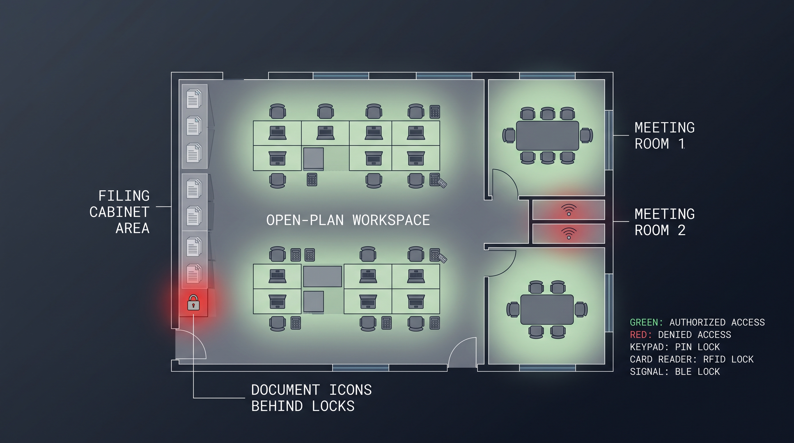
| Office cabinet | Motorized | RFID | 12 V DC | 0.35–0.6 N·m | $45–$90 |
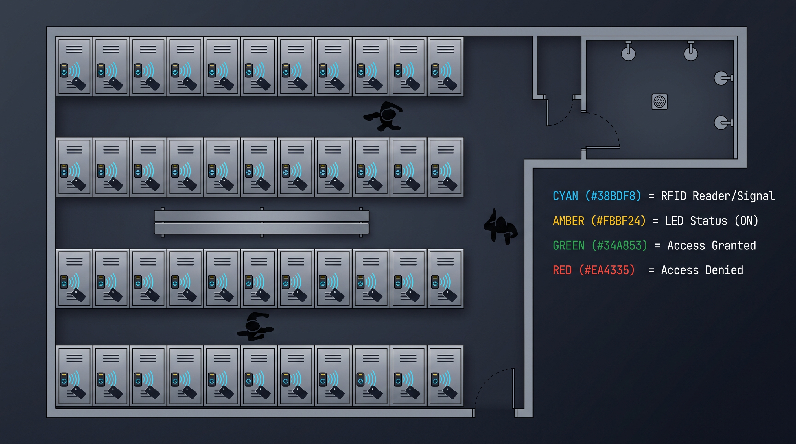
| Locker room | Motorized | RFID wristband or app | 6–12 V DC | 0.4–0.7 N·m | $50–$110 |
| Mailbox cluster | Solenoid | PIN | 6–12 V DC | 0.3–0.5 N·m | $25–$55 |
| Vending machine | Motorized | RFID + app | 12–24 V DC | 0.6–1.2 N·m | $60–$150 |
| ATM cassette | Motorized | RFID + PIN (two-factor) | 12 V DC | 0.8–1.5 N·m | $120–$180 |
| Pharma cabinet | Motorized | RFID + fingerprint | 12 V DC | 0.5–0.9 N·m | $100–$160 |
| Gun safe | Motorized | PIN + app | 6–12 V DC | 0.7–1.2 N·m | $80–$140 |
| Evidence locker | Motorized | RFID + PIN (two-factor) | 12 V DC | 0.6–1.0 N·m | $110–$170 |
| Retail display case | Solenoid | PIN | 6 V DC | 0.2–0.4 N·m | $25–$45 |
| Hotel safe | Motorized | RFID card | 6 V DC | 0.4–0.6 N·m | $55–$95 |
The table above provides a starting point for selection, but each application has unique requirements that may shift the recommendation. For example, a locker room in a high-humidity environment (swimming pool, spa) requires a lock with a corrosion-resistant coating and an IP65 or higher ingress protection rating, regardless of the actuator type. A vending machine in a public location with high vandalism risk requires a lock with a reinforced cam and a tamper switch that triggers an alarm if the cam is forced. A pharmaceutical cabinet subject to DEA or FDA regulations requires a lock with two-factor authentication and a non-erasable audit trail. The cost range in the table reflects the lock hardware only, not the supporting infrastructure — power supplies, network hubs, cable, and installation labor add 20 to 60 percent to the total project cost depending on the scale and complexity of the deployment.
Power Budget and Battery Life Calculation
For battery-powered electronic cam locks, the power budget is the constraining factor that determines battery life and maintenance interval. The calculation starts with the energy consumed per actuation cycle. For a motorized lock drawing 250 mA at 12 V for 0.6 seconds, the energy per actuation is 0.25 A × 12 V × 0.6 s = 1.8 watt-seconds, or 0.5 milliwatt-hours (mWh). For a typical day with 50 actuations, the daily energy consumption from the motor is 25 mWh. The lock's microcontroller, BLE radio, and RFID reader draw a quiescent current of 10 to 50 microamps in sleep mode, with the BLE radio advertising for 5 ms every 100 to 500 ms. At 30 µA sleep current and 12 V, the quiescent power is 0.36 mW, which consumes 8.6 mWh per day. The total daily energy consumption is 33.6 mWh. A 4-cell NiMH battery pack (4.8 V nominal, 2000 mAh) stores 9600 mWh of usable energy, providing a theoretical battery life of 9600 / 33.6 = 286 days, or approximately 9.5 months. In practice, battery self-discharge (5 to 15 percent per month for NiMH), voltage drop under load, and temperature effects reduce the usable life to 6 to 12 months. Lithium primary cells (CR123A or AA lithium) offer higher energy density (3000 to 3500 mWh per cell) and lower self-discharge (1 to 2 percent per year), extending battery life to 18 to 24 months. The lock's firmware should include a low-battery detection circuit that generates a warning alert when the battery voltage drops below the minimum operating threshold — typically 5.0 V for a 6 V system or 10.5 V for a 12 V system — giving the facility manager 2 to 4 weeks to replace the batteries before the lock becomes inoperable.
Technical Specifications Deep Dive: Torque, Cycles, and Certifications
Understanding the technical specifications of an electronic cam lock is essential for making an informed purchasing decision, and three specifications stand out as the most important: torque, cycle life, and certifications. Torque, measured in newton-meters (N·m), is the rotational force that the cam can apply to the strike plate. A torque of 0.35 N·m corresponds to approximately 3.1 inch-pounds, which is sufficient for a lightweight cabinet door with a single strike. A torque of 1.0 N·m (8.9 in-lb) is required for a heavy door with a compression gasket or a multi-point locking mechanism. The torque must be measured at the rated voltage — a lock that delivers 0.8 N·m at 12 V may deliver only 0.45 N·m at 6 V, and the lower torque may be insufficient to overcome the spring force of the strike plate. The torque rating is also affected by the gear ratio: a higher gear ratio increases torque but reduces actuation speed, and vice versa. Cycle life is the number of lock-unlock cycles the lock can perform before the probability of failure exceeds an acceptable threshold — typically 1 percent cumulative failure rate. For a solenoid lock, the cycle life is limited by the mechanical wear of the plunger guide and the cam stop, typically 100,000 to 200,000 cycles. For a motorized lock with a brass or sintered bronze gearbox, the cycle life is 200,000 to 500,000 cycles, and with a stainless steel gearbox and ceramic bearings, the cycle life can exceed 1,000,000 cycles. The cycle life specification assumes that the lock is operated within its rated voltage, temperature, and duty cycle limits. Operating a lock at 14 V in a 50 °C environment will reduce the cycle life by 50 to 70 percent compared to operation at 12 V and 25 °C. Certifications provide independent verification that the lock meets established standards. UL 294 is the most relevant certification for access control systems in North America, covering performance, endurance, and security. EN 14846 is the European standard for mechanical durability and security of locks and building hardware, with grades for cycling endurance, corrosion resistance, and security. CE marking indicates compliance with European health, safety, and environmental standards. RoHS certification confirms that the lock does not contain restricted hazardous substances such as lead, mercury, cadmium, and hexavalent chromium. For applications in the European Union, the CE and RoHS certifications are mandatory, while UL 294 is typically required for commercial installations in the United States and Canada.
Temperature, Humidity, and Environmental Ratings
The environmental rating of an electronic cam lock determines the range of conditions in which it can operate reliably. The operating temperature range is typically -10 °C to +50 °C for standard commercial locks, with extended-range models covering -30 °C to +70 °C for outdoor or cold-storage applications. The lock's electronics — microcontroller, RFID reader, BLE radio, and motor driver — generate heat during operation, and the internal temperature can rise 10 to 15 °C above the ambient temperature under continuous actuation. For outdoor installations, the lock should be rated for direct sunlight exposure, which can raise the surface temperature of a metal cabinet to 65 °C on a 35 °C day. The humidity rating is expressed as an IP (Ingress Protection) code. An IP54 rating provides protection against dust ingress and water splashes from any direction, which is sufficient for indoor cabinets and sheltered outdoor installations. An IP65 rating provides protection against low-pressure water jets and is recommended for washdown environments such as food processing facilities, laboratories, and outdoor mailboxes. An IP67 rating provides protection against temporary immersion in water up to 1 meter for 30 minutes, which is required for marine applications and flood-prone areas. The corrosion resistance of the lock body, cam, and fasteners is equally important. Zinc-alloy components with a nickel-plated or powder-coated finish provide adequate corrosion resistance for indoor use. Stainless steel components (304 or 316 grade) are required for outdoor, marine, or chemical-handling environments. The lock's internal electronics should be coated with a conformal coating (acrylic or silicone) to protect against condensation and corrosive atmospheres.
Network Connectivity and Remote Management
The network connectivity of an electronic cam lock determines whether it operates as a standalone device or as part of a centrally managed access control system. Standalone locks are programmed locally — credentials are enrolled by presenting a master card or entering a programming PIN at the lock itself — and they operate independently without any network connection. The advantage of standalone locks is simplicity: no network infrastructure, no server, no software license, and no IT involvement. The disadvantage is that credential management is manual: each lock must be programmed individually, and there is no remote lock/unlock capability, no real-time audit log, and no centralized alarm monitoring. Standalone locks are suitable for installations with fewer than 50 locks and low turnover of users. Networked locks connect to a central controller or a cloud-based platform via a wired or wireless interface. RS-485 is the most common wired interface for multi-lock installations, supporting up to 32 locks on a single bus with a cable length of up to 1200 meters. The RS-485 bus carries both power and data using a 4-conductor or 6-conductor cable, and each lock has a unique address set by DIP switches or software configuration. The central controller polls each lock periodically for status updates and audit log entries, and it can send unlock commands to individual locks or groups of locks. Wi-Fi connectivity is common for locks that are installed in locations where RS-485 wiring is not feasible, but the Wi-Fi radio consumes 100 to 300 mA during transmission, which significantly reduces battery life. Zigbee is a low-power mesh networking protocol that is well-suited for battery-powered electronic cam locks because the radio draws only 15 to 30 mA during transmission and the mesh topology allows locks to relay data from neighboring locks, extending the network range without additional infrastructure. The Zigbee range is 10 to 30 meters per hop, and a mesh network of 100 locks can cover a large facility with multiple floors. The cloud platform — typically a software-as-a-service (SaaS) subscription — provides the user interface for credential management, access scheduling, audit log reporting, and alarm notifications. The SaaS platform also handles firmware updates, which are pushed to the locks over the network, ensuring that all locks are running the latest security patches and feature releases.
Integration With Building Management Systems
An electronic cam lock system that is integrated with a building management system (BMS) or a physical security information management (PSIM) platform can provide centralized monitoring and control across multiple subsystems — access control, fire alarm, HVAC, lighting, and CCTV. The integration is typically done via a REST API, a BACnet gateway, or an ONVIF profile. The BMS can trigger an unlock command to all fail-safe locks in the event of a fire alarm, ensuring that egress paths are clear. It can also lock down specific zones during an active shooter event or a security breach, preventing access to sensitive areas. The CCTV system can be linked to the lock audit trail: when a specific lock is unlocked, the PTZ camera in that zone can be commanded to move to a preset position and begin recording. The HVAC system can adjust the temperature setpoint in a zone based on the occupancy status derived from lock activity — if a locker room has not been accessed in 4 hours, the HVAC can be set to an energy-saving mode. The integration requires that the electronic cam lock system exposes a standard interface — typically a REST API with JSON-formatted payloads — and that the BMS or PSIM platform supports the integration protocol. The API should support the following operations: unlock a specific lock, lock a specific lock, get the status of a specific lock (locked, unlocked, error, offline), get the audit log for a specific lock or a group of locks, enroll a new credential, revoke a credential, and set an access schedule. The API should authenticate requests using a secure token (JWT or OAuth 2.0) and should log all API requests for auditing purposes. The latency of the unlock command should be less than 500 milliseconds for a local network connection and less than 2 seconds for a cloud-based connection, measured from the time the unlock command is issued to the time the cam begins to rotate.
Installation Best Practices and Common Pitfalls
Installing an electronic cam lock requires attention to mechanical alignment, electrical wiring, and software configuration. The most common installation pitfall is misalignment between the cam and the strike plate. The cam must be positioned so that when the lock is in the locked state, the cam arm overlaps the strike plate by at least 5 mm, and when the lock is in the unlocked state, the cam arm clears the strike plate by at least 2 mm. If the cam is too high or too low, or if the throw angle is too small or too large, the lock will not engage properly, and the door will either rattle in the frame or fail to close. The alignment should be checked with the door both open and closed, because the weight of the door can cause the frame to sag slightly, changing the relative position of the cam and strike plate. The second most common pitfall is incorrect wiring polarity. Electronic cam locks are polarity-sensitive for the power input and, in some cases, for the data lines. Reversing the power polarity can damage the lock's electronics, and reversing the data line polarity can prevent communication. The wiring diagram should be consulted before connecting any wires, and the polarity should be verified with a multimeter before applying power. The third common pitfall is inadequate power supply sizing. The power supply must be rated for the total current draw of all locks connected to it, plus a safety margin of 20 to 30 percent. If the power supply is undersized, the voltage at the far end of the cable run may drop below the lock's minimum operating voltage, causing intermittent failures. The voltage drop can be calculated using the formula V_drop = 2 × I × R × L, where I is the current per lock, R is the resistance per meter of the cable, and L is the cable length in meters. For a 12 V system with 10 locks drawing 300 mA each, a 30-meter cable run, and 0.5 mm² cable (0.035 ohms per meter), the total voltage drop is 2 × 3.0 A × 0.035 ohms/m × 30 m = 6.3 V, which means the voltage at the far end is only 5.7 V — below the 6 V minimum for most locks. The solution is to use a thicker cable (1.5 mm², 0.012 ohms per meter) or to install local power supplies at the midpoint of the cable run.
Wiring and Cable Recommendations
| Cable Type | Conductor Gauge | Max Locks per Run | Max Cable Length (12 V, 5% drop) | Best For |
|---|---|---|---|---|
| 2-conductor shielded | 22 AWG (0.34 mm²) | 1–2 | 15 m | Short runs, single lock |
| 4-conductor shielded | 18 AWG (0.82 mm²) | 4–6 | 30 m | Medium runs, small groups |
| 6-conductor shielded | 16 AWG (1.31 mm²) | 8–12 | 50 m | Long runs, large groups |
| 2-conductor unshielded | 14 AWG (2.08 mm²) | 12–16 | 80 m | Very long runs, high current |
| CAT5e / CAT6 (PoD) | 24 AWG (0.20 mm²) | 1–2 | 25 m | Data + power over Ethernet |
| 2-conductor with drain wire | 20 AWG (0.52 mm²) | 2–4 | 20 m | Outdoor, shielded for EMC |
The cable type must be selected based on the current draw per lock, the number of locks on the run, and the required cable length. Shielded cable is recommended for installations near electrical equipment, fluorescent lighting, or radio transmitters, where electromagnetic interference could corrupt the data communication. The shield should be connected to ground at the power supply end only, not at both ends, to avoid ground loops. The drain wire (the bare wire that runs alongside the conductors) should be connected to the ground terminal of the power supply. For outdoor installations, the cable should be rated for direct burial or UV exposure, and the cable entry point into the lock should be sealed with a cable gland or silicone sealant to prevent water ingress. The wiring should be tested before the lock is fully assembled — apply power, verify that the cam rotates correctly, and check the communication between the lock and the controller using a diagnostic tool or a serial terminal.
Maintenance, Troubleshooting, and Lifecycle Management
An electronic cam lock requires periodic maintenance to ensure reliable operation over its expected service life of 5 to 10 years. The maintenance schedule depends on the actuation frequency, the environmental conditions, and the lock type. For a motorized lock in a high-traffic locker room (500 actuations per day), the cam and gearbox should be inspected and lubricated every 6 months. The recommended lubricant is a synthetic PTFE grease (e.g., Super Lube 21030) applied sparingly to the gear teeth and the cam pivot point. Over-lubrication can attract dust and debris, so a single drop per gear mesh is sufficient. For a solenoid lock, the plunger guide should be inspected for wear every 12 months. The solenoid coil resistance should be measured with a multimeter and compared to the manufacturer's specification — a deviation of more than 10 percent indicates a failing coil that should be replaced. The battery contacts should be cleaned with a contact cleaner (isopropyl alcohol or a dedicated electronics cleaner) every 12 months to remove oxidation that can increase contact resistance and reduce battery life. The most common troubleshooting scenarios are: the lock does not respond to any credential, the lock responds but the cam does not rotate, the cam rotates but does not reach the full throw, and the lock intermittently fails to unlock. For the first scenario — no response — the most likely cause is a dead battery or a disconnected power supply. Measure the voltage at the lock's power input terminals. If the voltage is below the minimum operating threshold, check the battery contacts, the power supply output, and the cable connections. For the second scenario — credential accepted but no rotation — the likely cause is a mechanical blockage of the cam or a failed motor. Remove the cam and check whether the cam rotates freely by hand. If the cam is stuck, the gearbox may be jammed, and the lock must be replaced. For the third scenario — partial rotation — the likely cause is insufficient voltage or a worn gearbox. Measure the voltage under load during actuation. If the voltage drops by more than 2 V below the no-load voltage, the power supply is undersized or the cable is too thin. For the fourth scenario — intermittent failures — the likely cause is a loose connection, a faulty sensor, or a firmware bug. Check all cable connections, tighten the terminal screws, and check the lock's firmware version and update if necessary.
End-of-Life and Replacement Cycle
The electronic cam lock replacement cycle is driven by two factors: the mechanical wear of the actuator and the obsolescence of the electronic components. The mechanical wear is predictable — the cam and gearbox have a finite cycle life, and when the lock approaches the end of its rated cycle life, the failure rate increases exponentially. The electronic components — microcontroller, memory, and radio — have a longer service life than the mechanical components, but they can fail due to electrostatic discharge, voltage spikes, or corrosion. The lock should be replaced when the actuation time increases by more than 50 percent from the baseline (e.g., from 0.5 seconds to 0.75 seconds), when the lock fails to complete the full rotation in more than 5 percent of actuations, or when the lock enters a fault state that requires a power cycle to clear. The replacement should be planned during a scheduled maintenance window to minimize downtime. The old lock should be removed following the same procedure as the retrofit installation, and the new lock should be pre-configured with the same credential database and access schedule to minimize re-enrollment effort. The audit log from the old lock should be downloaded before disposal, as it may contain evidence required for compliance purposes. The lock should be disposed of in accordance with local electronic waste regulations — the battery should be removed and recycled separately, and the electronic components should be processed by a certified e-waste recycler.
Future Trends: Electronic Cam Locks in the IoT Era
The electronic cam lock is evolving from a standalone access control device into a fully networked IoT sensor node that collects data on usage patterns, environmental conditions, and equipment status. The next generation of electronic cam locks will integrate environmental sensors — temperature, humidity, vibration, and magnetic door position — to provide a richer data set for facility management. A locker equipped with a sensor-equipped electronic cam lock can report not only who accessed it and when, but also the temperature inside the locker, whether the door was left ajar, and whether the locker was subjected to excessive vibration that could damage the contents. The lock will also be able to predict its own maintenance needs: by monitoring the motor current profile over time, the lock can detect when the gearbox friction is increasing and alert the facility manager to schedule lubrication before the lock fails. The credential interface will continue to evolve toward frictionless access — the user approaches the locker, and the lock authenticates them automatically via a BLE beacon or an ultra-wideband (UWB) ranging signal, without requiring the user to tap a card or enter a PIN. The UWB technology, which is already deployed in smartphone-based car access systems, provides sub-meter location accuracy and can unlock the correct locker as the user approaches, without any deliberate action. The lock will also support digital keys that can be shared and revoked instantly via the cloud, eliminating the need for physical credential distribution. The security of the lock firmware will be enhanced by secure boot, encrypted storage, and over-the-air (OTA) firmware updates with cryptographic signing. The lock will participate in a zero-trust access control architecture, where every access request is authenticated, authorized, and encrypted, and the lock can operate offline for extended periods by caching the credential database and syncing the audit log when connectivity is restored. The electronic cam lock, once a simple motorized replacement for a key and a cam, is becoming a smart, connected, and self-aware component of the intelligent building ecosystem.
Not sure which sensor fits your project?
Talk to our mmWave application engineers for a free consultation.
Find the right presence sensor for your hotel project
Compare the 3 protocols, check hotel-specific case studies, and download the installation guide
Related products
3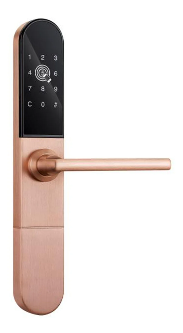
Smart Cabinet Lock — App-Managed, Multi-Site Dashboard
App-managed smart cabinet lock for office, parcel, and multi-site fleets. BLE app dashboard, audit trail, remote unlock, no per-lock server. Higher-tier chassis.
This page already points to it as the next recommended reference.
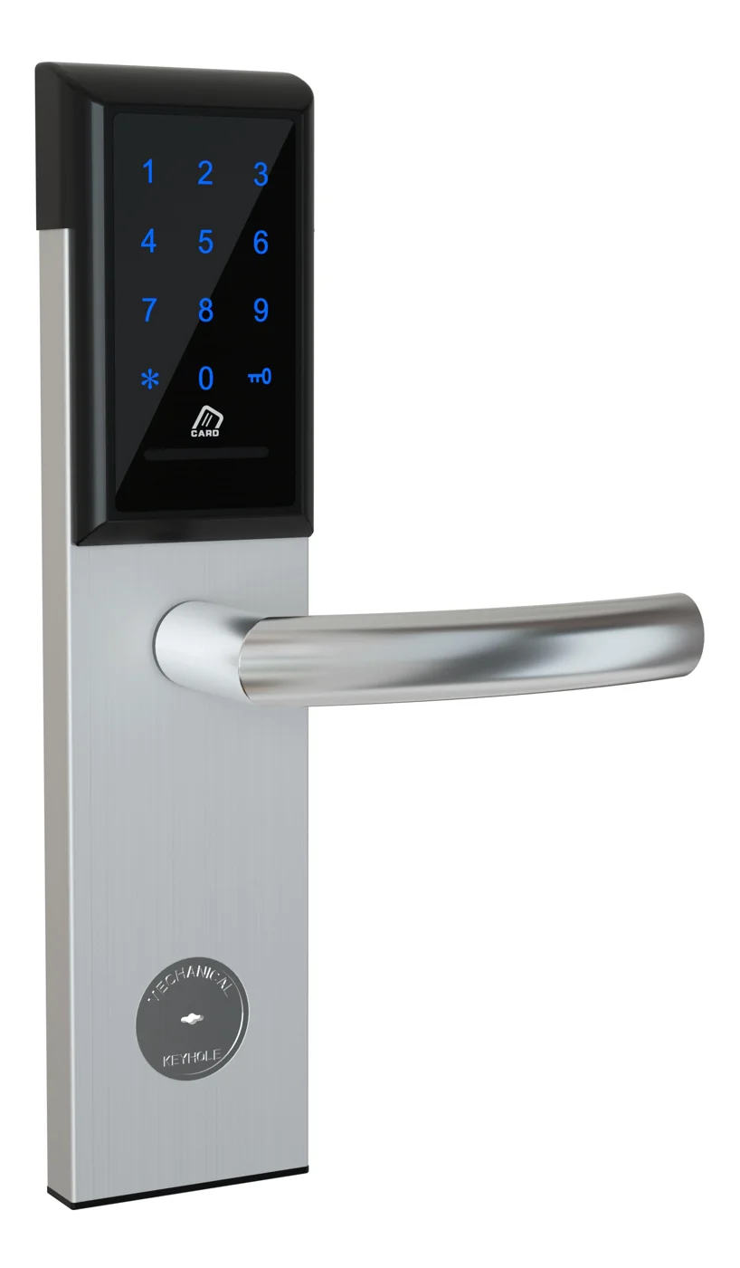
Office Cabinet Lock — PIN + Card for Filing & Pedestals
Offline PIN + card office cabinet lock for filing cabinets, pedestals, and drawers. Battery-powered 5-minute retrofit, no WiFi, no key management. CE/FCC/RoHS.
This page already points to it as the next recommended reference.
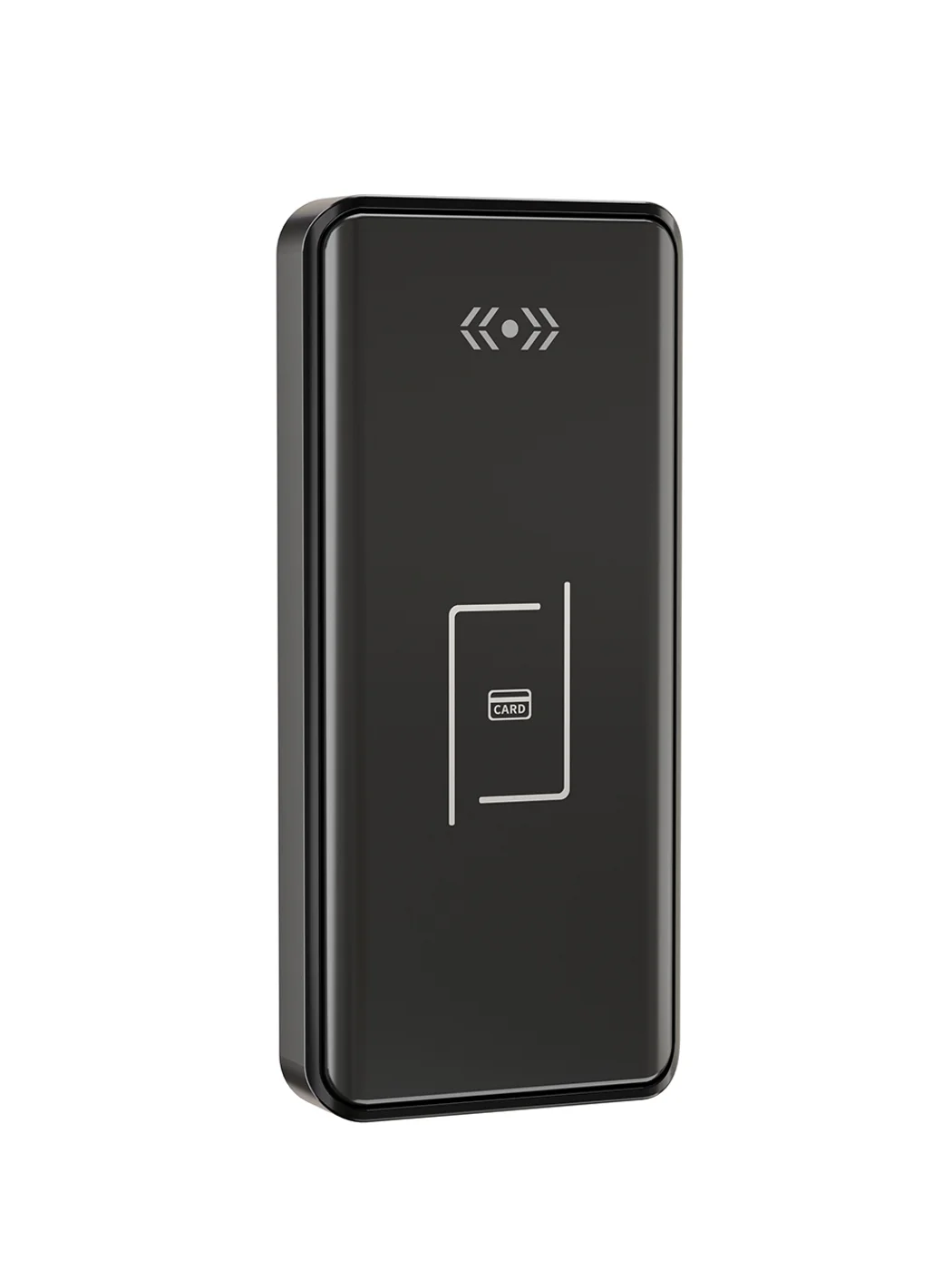
Gym Locker Lock — Offline Card, No WiFi Required
Offline card gym locker lock for fitness and pool lockers. MIFARE card, battery-powered 5-minute retrofit, no WiFi or server. Zinc alloy body, CE/FCC/RoHS.
This page already points to it as the next recommended reference.
Related blog posts
3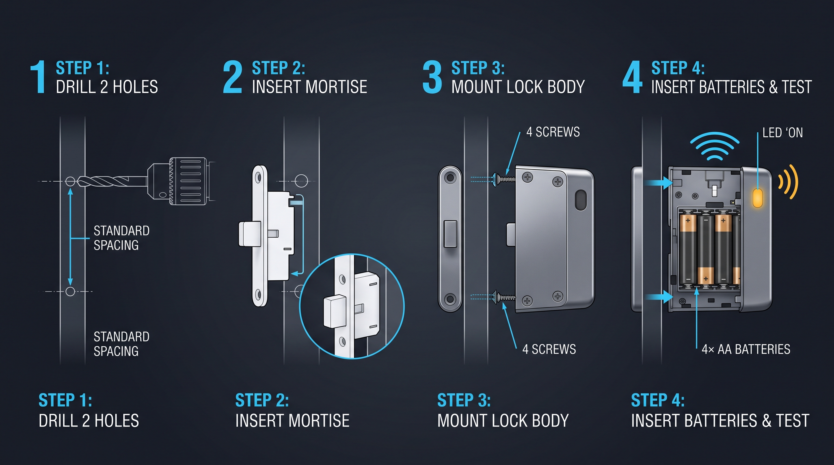
Electronic Locker Lock Price: Complete Guide to Cost Factors, Tiers, and Vendor Negotiation
Understand what drives an electronic locker lock price — from credential types and materials to volume discounts, NRE tooling, shipping, and 5-year TCO. Full pricing guide with tables.
It supports the same product context: Smart Cabinet Lock — App-Managed, Multi-Site Dashboard, Office Cabinet Lock — PIN + Card for Filing & Pedestals, Gym Locker Lock — Offline Card, No WiFi Required.
Electronic Locker Lock: The Complete 2026 Guide to Keyless Locker Security
Discover how an electronic locker lock works, from RFID to biometric models, with buying tips, specs, and comparisons for gyms, offices, and schools.
It supports the same product context: Gym Locker Lock — Offline Card, No WiFi Required.
Electronic Furniture Lock: The Complete Guide to Powered Cabinet Security
Electronic furniture lock secures cabinets, drawers, and casegoods with RFID, BLE, PIN, or biometric credentials, replacing keys with auditable, managed access. Full guide.
It supports the same product context: Office Cabinet Lock — PIN + Card for Filing & Pedestals.
Specify your hotel project with our engineers
Send your room count, ceiling type, and protocol preference. We will return a sample plan and quote within 24 business hours.
- Move from general guidance into a product or application discussion.
- Use RFQ when pricing, drawings, MOQ, or launch timing needs structure.
- Keep a direct contact path visible for fast clarifications and handoff.